
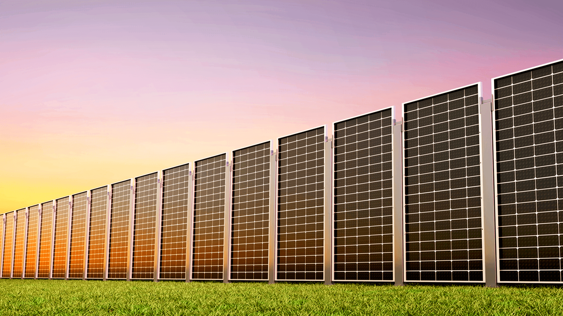
Spatial constraints on modern agricultural, commercial, and industrial sites have forced a reevaluation of traditional flat or tilted array topologies. Deploying a vertical solar mounting system can help make more efficient use of available land while allowing bifacial modules to receive irradiation from both sides. Integrating these upright arrays into utility-scale or commercial electrical grids requires careful alignment between mechanical racking, string sizing, and inverter MPPT configurations. Engineering teams specifying hardware from manufacturers like Antaisolar must account for distinct generation curves, elevated open-circuit voltages, and dynamic ground albedo reflections during electrical design phases.
Understanding the Electrical Characteristics of East-West Upright Arrays
Upright array configurations fundamentally alter the daily power generation profile compared to traditional south-facing tilted arrays. Rather than producing a singular midday generation peak, vertical orientations exhibit a distinct dual-peak generation curve that aligns closely with morning and afternoon energy demand cycles. Bifacial solar modules mounted vertically absorb direct radiation on both faces, capturing low-angle morning sunlight on the east face and afternoon light on the west face.
This dual-peak behavior introduces unique electrical dynamics across connected inverter channels. Because peak irradiation occurs at different times for each module surface, peak current levels are distributed more evenly throughout the day, mitigating midday clipping losses. However, high ground albedo from snow, light concrete, or suitable agricultural ground covers can increase rear-side irradiance and bifacial energy contribution. System designers must calculate total prospective string current by factoring in bifacial gain coefficients to avoid over-current conditions at the inverter input terminals.
String Sizing Calculations for Elevated Bifacial Voltages and Low Temperatures
Calculating optimal string length in vertical configurations demands evaluating open-circuit voltage behavior under extreme ambient temperatures. Photovoltaic module voltage rises as temperatures drop, requiring electrical engineers to determine maximum allowable series string counts based on the coldest historical site temperatures. Exceeding the maximum DC input voltage of the selected inverter risks damaging internal switching components and triggering emergency system shutdowns.
Upright installations often experience enhanced wind cooling due to increased convective air flow around vertically suspended panels. Lower operating cell temperatures increase operating voltage levels during peak winter irradiance windows. Using a vertical solar mounting system with an open structure can allow greater airflow around the modules, depending on the site and system geometry. Electrical engineers must adjust voltage calculation safety margins upward to prevent over-voltage trips during clear, cold morning conditions.
Inverter Selection Strategies: Multi-MPPT vs. Centralized Architectures
Matching inverter topologies to upright solar arrays requires evaluating how dynamic shading and variable solar orientation affect power tracking performance. Multi-MPPT string inverters offer significant performance advantages for upright structures by isolating individual module rows onto independent Maximum Power Point Trackers. This isolation prevents localized shading from low-lying vegetation or adjacent structures from reducing the output of unshaded panel strings.
Centralized inverter architectures can be utilized in vast, uniform installations where site topography is flat and row pitch is wide enough to prevent inter-row shading. However, string-level MPPT management remains superior for accommodating mismatched current outputs between east-facing and west-facing surfaces. Selecting multi-MPPT conversion hardware allows electrical engineers to balance string inputs dynamically, optimizing total daily power capture across variable weather and irradiance conditions.
Mitigating Inter-Row Shading and Mismatch Losses in Compact Footprints
Spacing vertical rows correctly balances land utilization efficiency against inter-row shading losses during extreme solar azimuth angles. When the Sun sits low on the horizon, tall upright mounting arrays cast extended shadows that can cross adjacent rows if the row pitch is designed too narrowly. Partial shading across a series-connected module string creates current bottlenecks, forcing bypass diodes to activate and reducing overall string operating voltage.
Addressing these mismatch losses involves pairing wide row spacing with smart electrical stringing techniques. String layout should be designed with the expected shading pattern and module electrical configuration in mind to limit mismatch losses where practical. Utilizing specialized structural hardware, such as the Antaisolar Vertical Ground Mount System, provides the structural foundation required to maintain precise row alignment, preventing structural sagging that could induce localized shading mismatches.
Cable Management and DC Distribution in High-Clearance Ground Structures
Managing DC cabling within vertical arrays requires specialized structural routing strategies due to elevated panel clearances and longer cable runs between posts. Exposed wiring in vertical systems faces direct exposure to wind shear, ultraviolet degradation, and mechanical stress from structural movement. Cable trays and internal post routing channels must shield string wiring from environmental factors while preserving clean aesthetic profiles across agricultural or industrial sites.
Because string inverters may be positioned at central distribution hubs rather than directly on racking posts, DC voltage drop becomes a crucial design factor. Longer cable runs require increasing DC conductor cross-sectional areas to minimize resistive power losses along the distribution line. Proper cable sizing helps keep voltage drop within the applicable design limits and reduces resistive losses.
Balance-of-System Optimization and Grid Interconnection Integration
Optimizing balance-of-system components for upright solar arrays requires a holistic approach that harmonizes structural engineering with electrical protection hardware. Fusing, DC disconnect switches, and surge protection devices must be rated for elevated bifacial short-circuit currents and potential voltage spikes. Properly specified electrical hardware prevents nuisance fuse trips caused by sudden albedo reflection spikes from surrounding ground surfaces.
Integrating a high-density vertical solar mounting system lowers balance-of-system costs by reducing site grading, civil trenching, and ground preparation expenditure. The dual-peak generation profile also offers grid interconnection benefits by smoothing out feed-in power distribution and reducing peak demand stress on local substation transformers. These technical and electrical advantages make upright arrays a highly viable solution for modern dual-use land projects.
Conclusion
Successfully deploying upright photovoltaic infrastructure requires appropriate matching between module string characteristics and inverter MPPT capabilities. Factoring in bifacial gain, temperature-induced voltage variations, and multi-MPPT string isolation allows project developers and EPC contractors to maximize energy yields within tight spatial boundaries. Partnering with primary manufacturers like Antaisolar provides commercial installers and developers with robust vertical mounting hardware engineered to maintain structural and electrical performance across decades of continuous grid operation.