
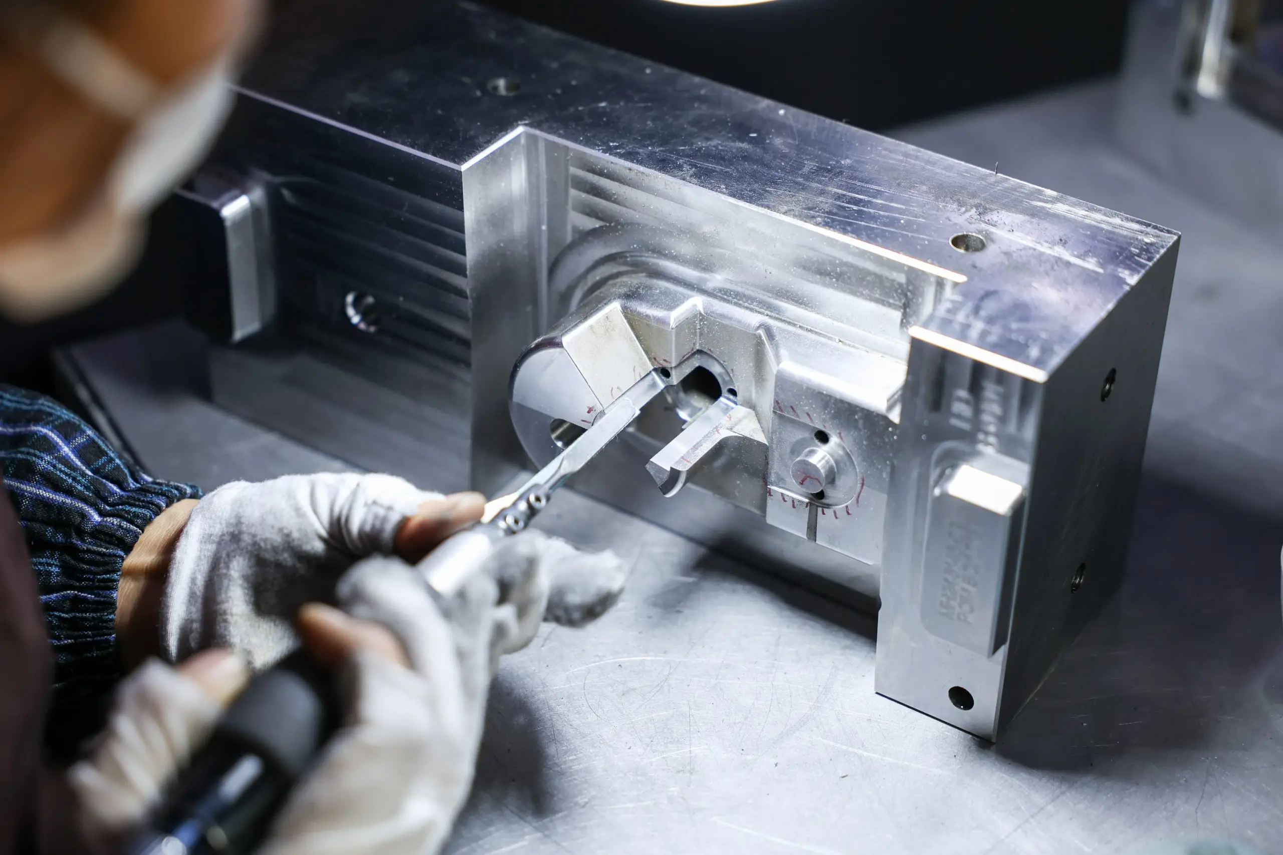
When a product moves from concept to physical validation, the challenge is not simply making a prototype. Engineers often need parts that reproduce the intended geometry, material behavior, surface appearance, and assembly performance closely enough to support meaningful testing. This is where indirect rapid tooling can provide a practical manufacturing route.
Unlike direct rapid tooling, which creates the production mold directly from the part design, indirect rapid tooling introduces an intermediate step: the master pattern. The pattern becomes the reference for creating a mold, which is then used to produce functional parts. This additional stage can offer greater flexibility when multiple prototype materials, mold configurations, or part variations need to be evaluated.
For projects involving complex development requirements, understanding the complete process from master pattern to final molded part helps teams select the right tooling strategy.
What Is Indirect Rapid Tooling?
Indirect rapid tooling is a manufacturing approach in which a master pattern is created first and then used to form or produce the mold needed for part manufacturing. The master pattern represents the desired geometry of the final component and serves as the physical reference for subsequent mold production.
The process can be useful when the master pattern needs to be preserved while different molding conditions or materials are evaluated. HordRT describes indirect rapid tooling as an option in which the master pattern is durable and can support different tooling approaches, including hard and soft tooling depending on the application.
The key difference is therefore the manufacturing sequence. Direct tooling moves more directly from CAD data to the functional mold, while indirect tooling adds a master pattern between product design and mold production.
Step 1: Creating the Master Pattern
The master pattern is the foundation of the entire indirect rapid tooling process. Its dimensions, surface quality, geometry, and detail reproduction directly influence the mold that follows.
Depending on the application, the master pattern can be manufactured using processes such as CNC machining or other suitable prototyping technologies. During this stage, engineers need to pay close attention to critical dimensions, surface finish, draft angles, parting areas, and other geometric features.
The purpose is not simply to make a visually similar prototype. The master pattern must accurately represent the geometry that the final mold is expected to reproduce.
For this reason, early design review is important. HordRT provides DFM analysis before tooling begins, allowing potential manufacturing risks to be identified before they become expensive downstream modifications.
Step 2: Using the Pattern for Mold Making
Once the master pattern has been verified, it becomes the reference for creating the mold. This is the defining stage of indirect rapid tooling.
The mold-making method depends on the required tool life, part complexity, production quantity, material requirements, and project budget. Soft tooling can be appropriate for simpler prototype applications and cost-conscious testing, while harder tooling can provide greater durability for applications requiring more repeated molding.
This stage transforms the geometry represented by the master pattern into a usable molding cavity. Mold structure, parting lines, runners, cooling, and ejection also need to be considered to ensure that the mold can produce parts consistently.
HordRT’s rapid tooling workflow includes mold design, tooling manufacture, fitting, assembly, and mold trial under one coordinated engineering process. Its tooling capabilities include aluminum, P20, NAK80, S136, H13, and project-specific steels, with material selection based on factors such as mold life, resin, geometry, and production requirements.
Step 3: Molding Functional Parts
After mold production and assembly, the mold is installed for the molding stage. Production-grade thermoplastics can then be processed to create functional components.
This is one of the major advantages of using a tooling-based prototype process. Instead of evaluating only an appearance model, engineering teams can examine parts produced through an actual molding process.
HordRT supports materials including ABS, PC, PC/ABS, PP, PA, POM, PMMA, PBT, TPE, TPU, and PPS. This range allows material selection to reflect the intended application rather than restricting evaluation to a single prototype material.
The resulting parts can therefore be used for dimensional inspection, assembly testing, functional evaluation, appearance review, and other development activities before larger-scale production.
Step 4: Inspecting and Validating the Final Parts
Molded parts are not the final checkpoint. Validation determines whether the tooling and molding process have reproduced the required design accurately.
HordRT’s quality process includes material verification, dimensional control, mold trial, T1 sample inspection, and final review. Depending on project requirements, inspection can include CMM dimensional measurement, 3D blue-light scanning, and T1 sample validation.
This feedback can reveal issues involving dimensions, surface quality, fit, appearance, or functional performance. If appropriate, tooling adjustments can then be made before the project advances toward subsequent production stages.
Why Consider Indirect Rapid Tooling?
The additional master pattern stage means indirect rapid tooling is not automatically the fastest option for every project. If a design is changing significantly, creating an intermediate pattern and mold can introduce additional time and cost.
However, the approach becomes attractive when the master pattern needs to be preserved, when different molding materials need to be tested, or when a project requires a flexible route between prototype development and functional part validation.
It can also provide a useful separation between the reference geometry and the molding tool. This can be valuable when teams need to experiment with tooling configurations without repeatedly rebuilding the original master pattern.
Why Choose HordRT for the Tooling Process?
HordRT connects engineering review, DFM analysis, toolmaking, molding, inspection, and validation within one manufacturing workflow. This reduces the need to coordinate every stage with separate suppliers and gives engineering teams a clearer path from design files to functional parts.
Its rapid tooling service offers a typical lead time of 5–10 working days, shared mold bases, production-grade materials, and no MOQ for flexible production. HordRT also reports more than 1,800 mold sets of annual tooling capacity and more than 100 precision tooling and CNC machines.
More importantly, its engineering-led approach connects the master pattern, mold design, manufacturing, trial, and inspection stages instead of treating them as isolated operations.
From Master Pattern to Production Confidence
Indirect rapid tooling creates a clear technical chain: master pattern → mold making → molding → inspection and validation → functional parts. Each stage has a specific role, and the quality of one stage directly affects the next.
For product teams evaluating geometry, materials, appearance, assembly, and functional performance before committing to larger production tooling, this process can provide a structured route to reliable prototype parts.
With DFM support, in-house toolmaking, flexible tooling options, production-grade molding materials, and integrated inspection, HordRT can help turn a carefully developed master pattern into functional molded parts ready for meaningful product evaluation.